Wireshark - TCP Packet Examination
Using Wireshark to examine and understand the Ethernet, IP, and TCP headers of a SYN packet
🦈 Wireshark is a network protocol analyser for macOS, Linux, and Windows. You can learn how to use Wireshark at Wireshark Learn. This post aims to explain a SYN packet capture in its entirety.
The Binary Dump
0000  10001010 10100101 10101010 10000000 10100000 00011010 10100000 01010111
0008  10100110 10011010 10101010 10101010 00001000 0000000001000101 00000000
0010  00000000 00110100 01011010 00101001 01000000 00000000 10000000 00000110
0018  00000000 00000000 11000000 10101000 00000001 00011110 00100011 10110010
0020  11000010 0100111011101000 00011111 00000001 10111011 11101101 10001100
0028  01100101 11111011 00000000 00000000 00000000 00000000 10000000 00000010
0030  11111010 11110000 10100111 11101101 00000000 00000000 00000010 00000100
0038  00000101 10110100 00000001 00000011 00000011 00001000 00000001 00000001
0040 00000100 00000010Above, we're looking at the binary dump for this particular packet. These are the 0s and 1s that are encoded as high and low voltage signals in wired connections, light pulses in fiber optic cables, and the modulation of radio waves in wireless communications.
Let's understand this dump first, starting with the four digit numbers on the left. These numbers are called offsets. They're added by Wireshark for our reference and are not actually contained in the packet.
Offsets are hexadecimal numbers that tell us how many bytes the beginning of the current line is from the beginning of the packet. For example, the third line of binary is offset 16 bytes into the packet, so the offset is 0010 (16 in hexadecimal).
Following each offset, you can see 8 bytes in binary. I've applied color-coded underlines to these bytes to distinguish them by their respective network layers and associated protocols.
Layer 2 Ethernet II bytes Layer 3 IPv4 bytes Layer 4 TCP bytesWireshark uses highlighting to differentiate layers and protocols in this way.
Let's look at the equivalent hexadecimal dump before examining each layer of the packet.
The Hexadecimal Dump
0000   8a a5 aa 80 a0 1a a0 57 a6 9a aa aa 08 0045 00   ·······W······E·
0010   00 34 5a 29 40 00 80 06 00 00 c0 a8 01 1e 23 b2   ·4Z)@·········#·
0020   c2 4ee8 1f 01 bb ed 8c 65 fb 00 00 00 00 80 02   ·N······e·······
0030   fa f0 a7 ed 00 00 02 04 05 b4 01 03 03 08 01 01   ················
0040   04 02                                             ··
Now, we're looking at the hexadecimal dump of the same packet.
The four digit numbers on the left are again the offsets. Because the actual data is now displayed in hexadecimal, twice as many bytes fit on a single line. Consequenty, you can see the offsets increment by 16 bytes instead of 8 bytes: 0010 (16), 0020 (32), 0030 (48), and so on.
At the end of each line, we can see the corresponding ASCII characters for the bytes in that line, if they're printable. This is to allow us to quickly see any readable text in a packet. SYN packets don't generally contain readable text, but take a look at the ASCII from a later packet:
06d0   17 00 2b 00 07 06 5a 5a 03 04 03 03 00 00 00 1a   ··+···ZZ········
06e0   00 18 00 00 15 77 77 77 2e 6d 61 74 68 65 77 6b   ·····www.mathewk
06f0   65 6e 6e 65 64 79 2e 63 6f 6d 44 69 00 05 00 03   ennedy.comDi····
0700   02 68 32 00 12 00 00 00 05 00 05 01 00 00 00 00   ·h2·············
The ASCII makes it a lot easier to identify certain parts of the packet, such as the server_name extension in the client hello above.
Note that the ASCII characters are also included in the binary dump in Wireshark, but there's more space to examine them here.
We're going to use two of Wireshark's panes to help us understand the content of each layer. In the packet detail pane, Wireshark adds labels and looks up or infers more information for us using protocol standards. The packet diagram pane gives a visual layout of the data.
Ethernet II Header (Layer 2)
These are the 14 bytes in the Ethernet II header of our original packet:
0000   8a a5 aa 80 a0 1a a0 57 a6 9a aa aa 08 0045 00   ·······W······E·
0010   00 34 5a 29 40 00 80 06 00 00 c0 a8 01 1e 23 b2   ·4Z)@·········#·
0020   c2 4e e8 1f 01 bb ed 8c 65 fb 00 00 00 00 80 02   ·N······e·······
0030   fa f0 a7 ed 00 00 02 04 05 b4 01 03 03 08 01 01   ················
0040   04 02
The packet diagram for Ethernet headers shows us what's in each byte:
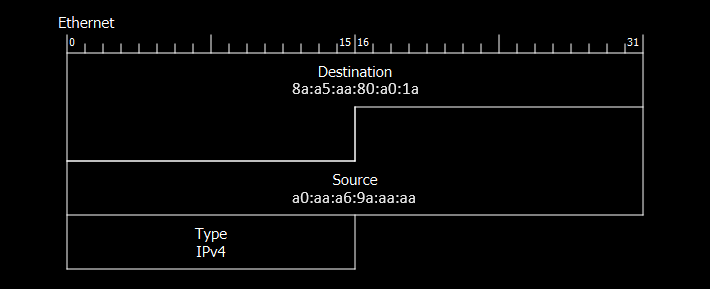
The diagram is 32 bits (4 bytes) wide, zero-indexed. We can see from the rows that the header contains:
- The destination MAC address (6 bytes)
- The source MAC address (6 bytes)
- The EtherType (2 bytes)
Here's how the packet detail pane displays this information:
Ethernet II, Src: IntelCor_9a:aa:aa (a0:57:a6:9a:aa:aa), Dst: HuaweiTe_80:a0:1a (8a:a5:aa:80:a0:1a)
    Destination: HuaweiTe_80:a0:1a (8a:a5:aa:80:a0:1a)
        Address: HuaweiTe_80:a0:1a (8a:a5:aa:80:a0:1a)
        .... ..0. .... .... .... .... = LG bit: Globally unique address (factory default)
        .... ...0 .... .... .... .... = IG bit: Individual address (unicast)
    Source: IntelCor_9a:aa:aa (a0:57:a6:9a:aa:aa)
        Address: IntelCor_9a:aa:aa (a0:57:a6:9a:aa:aa)
        .... ..0. .... .... .... .... = LG bit: Globally unique address (factory default)
        .... ...0 .... .... .... .... = IG bit: Individual address (unicast)
    Type: IPv4 (0x0800)
Destination and Source MAC Addresses
MAC addresses are assigned to a Network Interface Controller (NIC) to give that NIC a unique address within a network. They facilitate the "hop to hop" communication between the two devices a packet is currently being passed to and from. In this case the destination MAC address belongs to a NIC in my home router, and the source MAC address belongs to a NIC in my computer.
Devices can have multiple network interface controllers, some physical and some virtual, each with their own MAC address, meaning a single device often uses multiple MAC addresses for network communications. For example, your computer might have different NICs for WiFi, wired Ethernet, Bluetooth, and virtual private network (VPN) connections.
LG / IG Bits
The LG (Local/Global) bit is the second least significant bit (the second bit from the right) of the most significant byte (the first byte on the left) of the MAC address. It indicates whether the MAC address is locally administered (1) or globally unique (0).
In this case both MAC addresses are globally unique addresses assigned by the manufacturer. Locally administered MAC addresses are assigned by administrators within a local network. This allows flexibility, and the LG bit prevents interference with global uniqueness.
The IG (Individual/Group) bit is the least significant bit (the first bit on the right) of the most significant byte of the MAC address. It indicates whether the MAC address is an individual (unicast) address (0) or a group (multicast/broadcast) address (1).
In this case both MAC addresses are unicast.
- Unicast MAC addresses are used for communication between a single sender and a single receiver.
- Multicast MAC addresses are used for communication between a single sender and multiple specific receivers. Devices that want to receive multicast traffic must join a multicast group.
- The broadcast MAC address FF:FF:FF:FF:FF:FF is used for communication between a single sender and all devices on the network.
Wireshark displays the LG and IG bits visually using periods as the surrounding bits before the human-readable information.
OUI Bytes
The "HuaweiTe_" and "IntelCor_" prefixes are found by Wireshark in Wireshark's Manufacturer Database using the first, second, and third most significant bytes (the three left-most bytes) in each of the MAC addresses. These three bytes are the OUI (Organisational Unique Identifier) of any given MAC address, assigned to manufacturers by the IEEE.
EtherType
Type, or EtherType, indicates which protocol is encapsulated within this Ethernet frame. In this case it's IPv4.
Let's move on to examine that layer 3 IPv4 header.
IP Header (Layer 3)
These are the 20 bytes in the IP header of our original packet:
0000   8a a5 aa 80 a0 1a a0 57 a6 9a aa aa 08 00 45 00   ·······W······E·
0010   00 34 5a 29 40 00 80 06 00 00 c0 a8 01 1e 23 b2   ·4Z)@·········#·
0020   c2 4e e8 1f 01 bb ed 8c 65 fb 00 00 00 00 80 02   ·N······e·······
0030   fa f0 a7 ed 00 00 02 04 05 b4 01 03 03 08 01 01    ················
0040   04 02
Again, let's consult Wireshark's packet diagram of an IPv4 header to see what it contains.
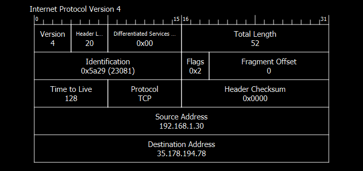
This packet contains:
- IP version and header length (1 byte)
- Differentiated Services (1 byte)
- Total length (2 bytes)
- Identification (2 bytes)
- Flags (3 bits)
- Fragment Offset (13 bits)
- Time to Live (1 byte)
- Protocol (1 byte)
- Header Checksum (2 bytes)
- Source IP address (4 bytes)
- Destination IP address (4 bytes)
Here's how the packet details pane displays the packet:
Internet Protocol Version 4, Src: 192.168.1.30, Dst: 35.178.194.78
    0100 .... = Version: 4
    .... 0101 = Header Length: 20 bytes (5)
    Differentiated Services Field: 0x00 (DSCP: CS0, ECN: Not-ECT)
        0000 00.. = Differentiated Services Codepoint: Default (0)
        .... ..00 = Explicit Congestion Notification: Not ECN-Capable Transport (0)
    Total Length: 52
    Identification: 0x5a29 (23081)
    010. .... = Flags: 0x2, Don't fragment
        0... .... = Reserved bit: Not set
        .1.. .... = Don't fragment: Set
        ..0. .... = More fragments: Not set
    ...0 0000 0000 0000 = Fragment Offset: 0
    Time to Live: 128
    Protocol: TCP (6)
    Header Checksum: 0x0000 [validation disabled]
    [Header checksum status: Unverified]
    Source Address: 192.168.1.30
    Destination Address: 35.178.194.78
Like with the LG bit and IG bit in the layer 2 header, Wireshark again uses periods, 1s, and 0s to indicate which bits the human-readable information pertains to.
IP Version and Header Length
We're using IP version 4 and the length of this IP header is 20 bytes. The 20 is actually sent as 5 for efficiency, meaning 5 * 4-byte words. This header length can vary, and the receiving device uses it to determine where to read from for the actual payload.
Differentiated Services Field
The Differentiated Services Field is split into two parts.
The first 6 bits are the Differentiated Services Codepoint (DSCP), which indicates the priority of the packet. Here, ours is set to 000000, which is the default, "Best Effort". In delay-sensitive traffic such as voice over IP, these 6 bits would typically be set to 101110 for Expedited Forwarding (EF). You can find a list of DSCP values in Cisco's DSCP and Precedence Values PDF.
The next 2 bits are used for Explicit Congestion Notification (ECN). Historically, when a router's queue filled up due to congestion, it started to drop packets, which served as an implicit signal to the sender that there was network congestion. The 2 ECN bits allow the endpoints to send explicit notifications of congestion without relying on packet dropping. In this example, our 2 bits are set to 00, which indicates that this traffic is not capable of using ECN. This can be due to the settings in the software application being used. The possibe values for these bits are:
- 00: Not ECN-Capable Transport (Non-ECT)
- 01: ECN-Capable Transport (ECT(1))
- 10: ECN-Capable Transport (ECT(0))
- 11: Congestion Experienced (CE)
01 and 10 both indicate ECN capability, but having two values allows more nuanced traffic management strategies.
Total Length
The "Total Length" field indicates the size of the 20-byte IP header plus the encapsulated data (here, a 32-byte TCP header). This sums to 52 bytes. To avoid fragmentation, this length must not exceed the Maximum Transmission Unit (MTU) of the receiving device, typically the router in a home network. Most router's have an MTU of around 1,500 bytes.
If a packet is fragmented, the total length field is also used in the reassembly of fragments by the receiving system, which reads the header and payload up to the length specified.
Identification
As mentioned above, if a packet is larger than the Maximum Transmission Unit of the receiving device, it is split into fragments. Each fragment's own IP header contains the same 16-bit "Identification" field value. Receiving hosts use this field to identify which fragments belong to the same original packet. Fragmentation is less common now, as modern systems send probing packets to determine the smallest MTU along the path to a destination. This is called the "Path MTU", and once it's discovered, the system can adjust packet size accordingly to prevent fragmentation.
Flags
These bits are used for fragmentation information.
- The first bit is always 0. It's called the reserved bit as it's reserved for future use.
- The second bit is the "Don't Fragment" (DF) bit. If this is set to 1, the packet should not be fragmented.
- The third bit is the "More Fragments" (MF) bit. This indicates whether there are more fragments to come for a given packet. It's set to 1 in all fragments with the same indentification value except the last.
Fragment Offset
This field indicates a fragment's offset in 8-byte blocks from the start of its original packet (not including IP headers). This allows receiving devices to place the data correctly during reassembly.
Let's say we've divided a packet into fragments of 1,500 bytes each. That 1,500 bytes includes the 20 byte IP headers, so the data portion in each fragment will be 1,480 bytes.
First Fragment:
- Header Length: 20 bytes
- Data Length: 1,480 bytes
- Fragment Offset: 0 (since this is the start of the original data)
Second Fragment:
- Header Length: 20 bytes
- Data Length: 1,480 bytes
- Fragment Offset: 1,480 / 8 = 185 (since the data starts 1,480 bytes into the original packet.)
Time to Live
The Time to Live (TTL) field specifies the maximum number of hops (or routers) that a packet can pass through before being discarded. It helps prevent packets from circulating endlessly in the network due to routing loops.
When a packet is created and sent, the TTL value is set to a default number, commonly 64, 128, or 255, depending on the operating system or network configuration. Each time the packet is processed by a hop, the TTL value is decremented by 1. When it reaches 0, the packet is discarded.
Protocol
This indicates which protocol is encapsulated within this IP header. In our case, that's TCP (Transmission Control Protocol), represented by the number 6.
Header Checksum
The checksum ensures data integrity. It is calculated by:
- Splitting the IP header into 16-bit words
- Summing these binary numbers using "end-around-carry", which means if the sum exceeds 16 bits, overflow bits are carried from the most significant bit on the left to the least significant bit on the right.
- Inverting the binary with a bitwise NOT
The receiving device recalculates the checksum and compares it to the one in this header. If it doesn't match, it means the header may have been corrupted during transmission.
In our case, 0x0000 indicates that validation is disabled. This is due to "checksum offloading", where the Network Interface Controller hardware handles validation.
Source and Destination IP Addresses
At the end of the IP header, we have the source and destination IP addresses. These addresses identify hosts, or end devices, on a network. While MAC addresses facilitate "hop to hop" communication, IP addresses facilitate "host to host" communication.
Here, the desination address is the public IP address for one of my servers.
The source address is a private IP address assigned to my computer by my home router. Private IP addresses are not used on the public internet, as they're not unique. When my router processes this packet, it will replace the private source IP address in the IP header with its own unique public IP address using Network Address Translation (NAT), more specifically Port Address Translation (PAT). It keeps track of this change in an Address Translation Table. When my server responds with packets, the destination IP address in the IP headers will be my router's public IP address. My router will use the Address Translation Table to change the destination IP address to my computer's private IP address before sending the packet on to my computer's NIC.
PAT allows all devices in a local network to use the same public IP, conserving unique IPv4 addresses. IPv6 is slowly replacing IPv4, and IPv6 addresses won't run out - they're 128 bits long, so we've got 2128 (340 undecillion) of those.
PAT also changes port numbers in the TCP header at layer 4 (which we'll look at next) in order to keep unique mappings in the router's Address Translation Table.
TCP Header (Layer 4)
These are the 32 bytes in our TCP header:
0000   8a a5 aa 80 a0 1a a0 57 a6 9a aa aa 08 00 45 00   .......W......E.
0010   00 34 5a 29 40 00 80 06 00 00 c0 a8 01 1e 23 b2   .4Z)@.........#.
0020   c2 4e e8 1f 01 bb ed 8c 65 fb 00 00 00 00 80 02  .N......e.......
0030   fa f0 a7 ed 00 00 02 04 05 b4 01 03 03 08 01 01  ................
0040   04 02                                            ..
Here's Wireshark's packet diagram for the TCP header.
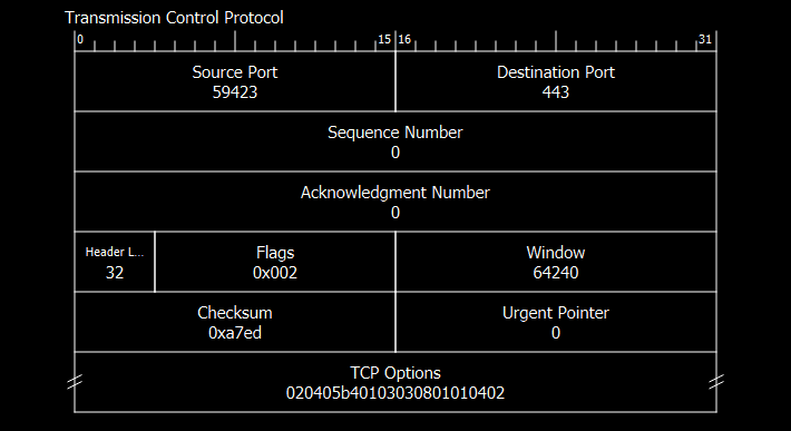
This header contains:
- Source port (2 bytes)
- Destination port (2 bytes)
- Sequence number (4 bytes)
- Acknowledgement number (4 bytes)
- Header length (4 bits)
- Flags (12 bits)
- Window (2 bytes)
- Checksum (2 bytes)
- Urgent pointer (2 bytes)
- TCP options (Variable, 0 - 320 bits, discussed in detail later)
Here's how the packet details pane displays the header:
Transmission Control Protocol, Src Port: 59423, Dst Port: 443, Seq: 0, Len: 0
    Source Port: 59423
    Destination Port: 443
    [Stream index: 14]
    [Conversation completeness: Incomplete, DATA (15)]
    [TCP Segment Len: 0]
    Sequence Number: 0    (relative sequence number)
    Sequence Number (raw): 3985401339
    [Next Sequence Number: 1    (relative sequence number)]
    Acknowledgment Number: 0
    Acknowledgment number (raw): 0
    1000 .... = Header Length: 32 bytes (8)
    Flags: 0x002 (SYN)
        000. .... .... = Reserved: Not set
        ...0 .... .... = Accurate ECN: Not set
        .... 0... .... = Congestion Window Reduced: Not set
        .... .0.. .... = ECN-Echo: Not set
        .... ..0. .... = Urgent: Not set
        .... ...0 .... = Acknowledgment: Not set
        .... .... 0... = Push: Not set
        .... .... .0.. = Reset: Not set
        .... .... ..1. = Syn: Set
        .... .... ...0 = Fin: Not set
        [TCP Flags: ··········S·]
    Window: 64240
    [Calculated window size: 64240]
    Checksum: 0xa7ed [unverified]
    [Checksum Status: Unverified]
    Urgent Pointer: 0
    Options: (12 bytes), Maximum segment size, No-Operation (NOP), Window scale, No-Operation (NOP), No-Operation (NOP), SACK permitted
        TCP Option - Maximum segment size: 1460 bytes
            Kind: Maximum Segment Size (2)
            Length: 4
            MSS Value: 1460
        TCP Option - No-Operation (NOP)
            Kind: No-Operation (1)
        TCP Option - Window scale: 8 (multiply by 256)
            Kind: Window Scale (3)
            Length: 3
            Shift count: 8
            [Multiplier: 256]
        TCP Option - No-Operation (NOP)
            Kind: No-Operation (1)
        TCP Option - No-Operation (NOP)
            Kind: No-Operation (1)
        TCP Option - SACK permitted
            Kind: SACK Permitted (4)
            Length: 2
    [Timestamps]
        [Time since first frame in this TCP stream: 0.000000000 seconds]
        [Time since previous frame in this TCP stream: 0.000000000 seconds]
Source and Destination Ports
Where MAC addresses facilitate "hop to hop" communication, and IP addresses facilitate "host to host" communication, ports facilitate what we might call "service to service" communication.
If you're using a browser and Slack desktop at the same time, all requests sent by both of these services will have the same source MAC address in their layer 2 header, and the same source IP address in their layer 3 header. Port numbers here at layer 4 differentiate connections.
In our example above, the source port is 59423. My browser process used the Windows Sockets API to "bind" to the local address 192.168.1.30:59423 (a local IP and port pair).
The destination port is port 443. Upon processing this TCP header, my server's operating system will pass the encapsulated data to whichever software is "listening" for incoming connections on the address 35.178.194.78:443, which in this case is nginx (web server software).
When the browser initiates a connection to my server, my home computer's operating system establishes a socket representing the full connection, which is uniquely identified by the 5-tuple: the source IP address, the source port, the destination IP address, the destination port, and the protocol. So this would be:
(192.168.1.30,59423,35.178.194.78,443,TCP)
The browser can now use the socket to send and receive data via the operating system.
As mentioned above, my router changes the source port in outbound TCP headers as part of Port Address Translation. This ensures a unique mapping between the private and public IP address in the router's Address Translation Table. When my router receives responses, it will use the Address Translation Table to return the original port and IP address to the headers, ensuring my operating system can send data to 192.168.1.30:59423 for the browser.
Stream Index, Conversation Completeness, TCP Segment Length
Stream index, conversation completeness, and TCP segment length are calculated by Wireshark and are not in the TCP header.
"Stream index" is a number Wireshark assigns to "conversations". Packets are part of the same conversation in Wireshark if they're sent using the same layer 4 protocol, between the same two IP addresses, using the same port numbers. This SYN packet is the first of a conversation (0).
"Conversation completeness" is calculated using the TCP flags, so we can discuss it in detail in the TCP Flags section.
"TCP segment length" is 0, because there's no actual data encapsulated in this SYN TCP header. The "three way handshake" we're initiating uses data in the TCP header itself.
Sequence Number and Acknowledgement Number
The sequence number tracks the bytes that are sent, and the acknowledgement number tracks the bytes that are received.
When we send data, we add a sequence number, for example 3985403374. This is pseudo-randomly generated to make it hard to guess. When the recipient receives the data from the segment with that sequence number, they send back an acknowledgement number equal to that sequence number plus the bytes received. This happens in both directions of communication.
As an example, say we send the sequence number 3985403374 to my server, and the TCP Segment Length we're sending is 64 bytes, the server will respond with an acknowledgement number of 3985403438 (3985403374 + 64). This acknowledgement number will be used as our next sequence number. If either party doesn't receive an acknowledgement number it's expecting within a given time, it will resend the segment with that sequence number. If either party receives a duplicate segment, it will resend the appropriate acknlowedgement.
The pseudo-random initial sequence numbers are quite large, so Wireshark displays "relative" sequence and acknowledgement numbers that start at 0 for each conversation.
Header Length
This is the size of this TCP header not including encapsulated data. Here ours is 32 bytes, sent as 8 (8 * 4-byte words, as with IP header length at layer 3).
TCP Flags
These flags are used to indicate the state of the TCP connection.
The first three reserved bits are again for future use and always set to 0.
The ECN-Echo and Congestion Window Reduced flags are used if there's network congestion. If a router experiences congestion and the ECN flag in the IP header is set to ECN-Capable, the router will set that flag to 11 (CE - Congestion Experienced), and forward the packet instead of dropping it. When the host receives the packet, it will detect the CE flag in the IP header and set the ECN-Echo flag in it's next TCP acknowledgement segment. When the sender receives the acknowledgement with the ECN-Echo flag set, it will set the Congestion Window Reduced flag in it's next segment to confirm it has reduced its window.
Note here that TCP software (layer 4) is reading an IP header's ECN flag (layer 3). This is an example of how, even though it's essential to minimise interaction between layers to maintain modularity and encapsulation, some controlled interactions are acceptable.
The Syn (Synchronise) and Ack (Acknowledgement) flags are are set as appropriate in the SYN → SYN ACK → ACK segments of the three way handshake, where hosts are initialising their sequence and acknowledgement numbers.
To understand Push and Urgent flags, we need to understand the buffers that hosts maintain during a TCP connection.
Senders maintain a buffer of unacknowledged data (in case it needs to be resent) and data yet to be sent. When data is acknowledged by the receiver, it can be deleted from the buffer.
Receivers maintain a buffer containing data that is yet to be processed, or data that is received out of order and awaiting missing segments.
For efficiency, both buffers wait until a certain amount of data has built up to either send that data out as a segment or to pass it to the appropriate application.
The Push flag tells the sender and receiver to process their data immediately. All data in the buffers are processed, and so data is still sent in sequence.
The Urgent flag tells the sender and receiver to process only the data specified by the Urgent Pointer (explained below) immediately. The rest of the buffer is unaffected and so the urgent data is sent out of sequence.
Reset and Fin are set to 1 to reset or terminate the connection, respectively.
Window
The TCP window size, also known as the "receive window size" or "advertised window size", represents the amount of buffer space available at the receiver for incoming data. It indicates how much data the sender can transmit before needing an acknowledgment from the receiver.
Checksum
The TCP checksum is calculated using the TCP header, the encapsulated data, and a pseudo-header containing the protocol and both IP addresses. This checksum is calculated with the same operations used to calculate the IP checksum explained previously.
Because the IP addresses are needed for the pseudo-header in this calculation, the layer 4 TCP software of a network stack must access information from the layer 3 IP header. This is another example of controlled interactions between network layers.
Urgent Pointer
The urgent pointer indicates the offset in bytes from the current sequence number to the end of the urgent data discussed in the TCP flags section.
Options
TCP options allow us to modify or enhance the standard behaviour of the protocol.
Maximum Segment Size is the largest TCP segment size (in bytes) the sender can receive without fragmentation. This doesn't include the TCP or IP header. In our example mine is 1,460 bytes.
The Window Scale option allows for larger window sizes than the standard 16-bit Window field can accommodate. By shifting the 16-bit base Window value to the left, we can multiply the window size by 2.
In our example, the 16-bit base Window size is 11111010 11110000 (64,240 in decimal, so 64,240 bytes). Our Window Scale shift count is 8, so we shift bits 8 positions to the left:
00000000 11111010 11110000 (64,240)
   <-       <-       <-    shift left 8 positions
11111010 11110000 00000000 (16,445,440)
This is the equivalent of multiplying our base Window value by 256.
The SACK permitted option means "Selective Acknowledgement" is permitted. Without this option, TCP uses "Cumulative Acknowledgement" as described in the Sequence Number and Acknowledgement Number section. Cumulative acknowledgement essentially says "I've received everything up to this point". This means that if a packet is lost and resent out of sequence for any reason, the receiver will send a late acknowledgement for that packet, and the sender will retransmit all data that followed the lost packet, even if it's already been received.
SACK permitted, when set in the initial SYN packet of a three way handshake, is allowing the receiver to modify it's acknowledgement field to acknowledge data out of sequence to avoid this unecessary retransmission.
The "No-Operation" options are 1 byte options used to "pad" the data so that all options are 32-bits in length. 32 bit options can be parsed more efficiently by modern software and hardware. This is why the IP and TCP Header Length values also multiply 4-byte (32 bit) words.
That's it for this SYN packet! Keep checking back to my blog where I plan to write other networking posts about QUIC, OSI layers 5 - 7, and the TLS 1.3 handshake.
Thanks so much for reading. I hope this helped you to understand network layers and protocols in more depth, or served as a nice refresher. 🛜🧠